ISDN原理及DDR配置实验
6.1 实验目的:
1. 掌握DDR的两种方式―标准DDR和灵活DDR;
2. 熟悉ISDN的基本原理;
3. 熟悉DDR拨号的应用。
6.2 实验环境:
在实验室中,我们用一台交换机模拟一个局域网,路由器作为局域网的出口向其他局域网的路由器拨号进行连接。路由器通过modem连接至PSTN网。具体组网如下图所示:
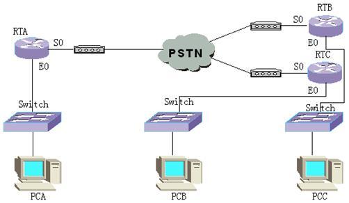
此实验采用异步modem,其配置与采用同步modem有些差异,在实验中会有介绍。由于路由器与modem之间的连接没有专用线缆,需要采用modem线和V.24线缆一起连接。
6.3 实验步骤:
6.3.1 标准DDR
在串口直接使能标准DDR
首先我们来完成一个最简单的实验,在实验组网中我们只配置RTA和RTB,使其能够互相拨号连接,采用直接在物理接口S0使能标准DDR的方式。
配置步骤如下:
1. 配置dialer-list;
2. 配置物理接口IP地址;
3. 使接口工作在异步模式;
4. 设置接口是接受还是发送呼叫;
5. 使能标准DDR;
6. 使接口与dialer-list关联;
7. 配置拨号串。
完成上述配置后查看配置信息如下:
RTA#show running-config
Now create configuration...
Current configuration
!
version 1.5.6
dialer-list 1 protocol ip permit //配置dialer-list
hostname RTA
!
interface Aux0
async mode interactive
encapsulation ppp
!
interface Ethernet0
speed auto
duplex auto
no loopback
!
interface Serial0
physical-layer async //置异步模式
modem //设置既可接受呼叫也可发出呼叫
async mode dedicated
encapsulation ppp
ip address 1.0.0.1 255.255.255.0
dialer in-band //使能标准DDR
dialer-group 1 //使接口与dialer-list关联
dialer string 2342 //配置拨号串
!
interface Serial1
encapsulation ppp
!
end
RTB#show running-config
Now create configuration...
Current configuration
!
version 1.5.6
dialer-list 1 protocol ip permit
logging console
hostname RTB
!
interface Aux0
async mode interactive
encapsulation ppp
!
interface Ethernet0
speed auto
duplex auto
no loopback
!
interface Serial0
physical-layer async
modem
async mode dedicated
encapsulation ppp
ip address 1.0.0.2 255.255.255.0
dialer in-band
dialer-group 1
dialer string 2136
!
interface Serial1
encapsulation ppp
!
end
此时,我们可以在路由器RTA和RTB上用测试命令ping测试是否能够正常建立拨号连接。打开调试信息开关(debug dialer event;debug dialer packet),我们会看到如下信息:
RTB#ping 1.0.0.1
PING 1.0.0.1: 56 data bytes, press CTRL_C to break
Request time out
Request time out
Request time out
Request time out
Request time out
--- 1.0.0.1 ping statistics ---
5 packets transmitted
0 packets received
100.00% packet loss
RTB#
DDR: try to find routing to 1.0.0.1 on interface Serial0
DDR: it is an interesting packet
DDR: there is not a dialer map matching this address
DDR: Find a dialer string
DDR: Try to find a free channel to dial 2136: on the interface
DDR: Dialing 2136 on interface Serial0 of interface Serial0
DDR: discard this packet
DDR: try to find routing to 1.0.0.1 on interface Serial0
DDR: it is an interesting packet
……
DDR: there is not a dialer map matching this address
DDR: Find a dialer string
DDR: A Link is connecting by this dialer map, waiting this Link
DDR: discard this packet
% Interface Serial0 changed state to UP
%MODEM: Serial0 changed state to UP.
DDR: Receive CALL_CONN_CFM
DDR: link layer ask the PPP_interface of the interface Serial0
DDR: Link layer transfer NAME '' to DDR on interface Serial0
DDR: NAME authentication OK
% Line protocol ip on interface Serial0, changed state to UP
DDR: link negotiation Up on interface Serial0
DDR: peeraddr matching success on interface Serial0 ,link UP
再次测试,看看是什么情况?是不是已经可以ping通对端了?并且有如下调试信息:
DDR: try to find routing to 1.0.0.1 on interface Serial0
DDR: it is an interesting packet
DDR: there is not a dialer map matching this address
DDR: Find a dialer string
DDR: Find a Up Link on interface Serial0, success!
注意实验现象,第一次测试时,路由器和modem正处于拨号阶段,并可以在此过程中听到modem的拨号音。等待一会儿后链路状态变为UP,建立起连接,再次测试时就可以ping通对端了,这是因为在路由器间已经有Up Link可用。
我们刚才测试时ping的是对端路由器S0口的IP地址,如果我们给以太口配置上IP地址,然后ping以太网地址呢?是不是不能ping通了,看看调试信息,知道为什么吗?因为我们还没有配置路由。在路由器RTA和RTB上配置静态路由,完成如下几条命令:
RTA(config-if-Ethernet0)# ip address 10.110.32.1 255.255.248.0
RTA(config)# ip route 10.110.10.0 255.255.255.0 1.0.0.2
RTB(config-if-Ethernet0)# ip address 10.110.10.100 255.255.255.0
RTB(config)# ip route 10.110.32.0 255.255.248.0 1.0.0.1
然后再次测试,应该可以ping通对端以太网口了。如果正确配置主机的IP地址和缺省网关后,主机间也应该能够互通了。
为了提供或改变我们使用DDR的效果,可以修改一些DDR的特性参数。首先我们可以使用show dialer interface serial 0查看Quidway路由器的默认配置如下:
RTB#show dialer interface serial 0
Serial0 - dialer type = Serial
NextHop_address Dialer_Strings
Dialer string 2136
Idle timer (120 secs), Fast Idle timer (20 secs)
Wait for carrier (60 secs), Re_enable (20 secs)
Autodial interval (300 secs)
这些参数都可以在接口模式下进行修改。请参照教材修改参数,熟悉相关命令和参数的作用。另外值得注意的是在调试输出信息中总是提示discard this packet,这是由于我们没有配置缓冲区的缘故,在接口模式下配置缓冲区(dialer hold-queue queue-length)后,在没有建立连接的情况下,触发拨号,看看路由器的调试信息有什么变化?这在实际配置中将有重要地位,因为在实际网络中是不希望把开始触发拨号的数据包丢弃的,所以我们需要配置合适的缓冲区来缓存建立拨号连接过程中所收到的数据包,待连接建立之后再发送出去。
使用逻辑接口Dialer interface实现连接
上面的实验我们采用的是直接在物理接口使能DDR,实际上还可以应用逻辑接口来实现。下面我们用逻辑接口的方式来实现同样的功能。具体配置步骤如下:
1. 配置dialer-list;
2. 创建逻辑接口;
3. 给逻辑接口配置IP地址;
4. 使能标准DDR;
5. 使逻辑接口与dialer-list关联;
6. 配置拨号串;
7. 将串口设置成拨号口;
8. 将物理接口与逻辑接口捆绑在一起;
9. 配置以太口IP地址;
10. 配置静态路由。
完成上述配置后的配置信息如下:
RTA#show running-config
Now create configuration...
Current configuration
!
version 1.5.6
dialer-list 1 protocol ip permit
hostname RTA
!
interface Aux0
async mode interactive
encapsulation ppp
!
interface Ethernet0
speed auto
duplex auto
no loopback
ip address 10.110.32.1 255.255.248.0
!
interface Serial0
physical-layer async
modem
async mode dedicated
encapsulation ppp
dialer in-band
dialer-group 1
dialer rotary-group 0 //捆绑逻辑接口和物理接口
!
interface Serial1
encapsulation ppp
!
interface Dialer0
ip address 1.0.0.1 255.255.255.0
dialer in-band
dialer-group 1
dialer string 2342
!
interface Dialer1
dialer in-band
!
exit
ip route 10.110.10.0 255.255.255.0 1.0.0.2 preference 60
!
end
路由器RTB作类似配置,与上一个实验的IP地址分配一样。现在测试是否能正常发送和接受呼叫?答案是肯定的。此处物理接口的配置比较简单,实际上它的配置属性都是从逻辑接口Dialer 0继承过来的。
点到多点连接
在前面的两个实验都是点到点的连接,那么点到多点连接有没有不同呢?让我们完成如下实验来学习、掌握点到多点的连接。按照组网图建立实验环境,实验要求RTA能与RTB、RTC互相呼叫,但RTB与RTC不能互相呼叫。具体的配置步骤自己思考,下面是完成后的配置信息:
RTA#show running-config
Now create configuration...
Current configuration
!
version 1.5.6
dialer-list 1 protocol ip permit
logging console
hostname RTA
!
interface Aux0
async mode interactive
encapsulation ppp
!
interface Ethernet0
speed auto
duplex auto
no loopback
ip address 10.110.32.1 255.255.248.0
!
interface Serial0
physical-layer async
modem
async mode dedicated
encapsulation ppp
ip address 1.0.0.1 255.255.255.0
dialer in-band
dialer-group 1
dialer map ip 1.0.0.2 2342 //对不同目的地设置拨号串
dialer map ip 1.0.0.3 2886
!
interface Serial1
encapsulation ppp
!
exit
ip route 10.110.0.0 255.255.255.0 1.0.0.3 preference 60
ip route 10.110.10.0 255.255.255.0 1.0.0.2 preference 60
!
end
RTB#show running-config
Now create configuration...
Current configuration
!
version 1.5.6
dialer-list 1 protocol ip permit
logging console
hostname RTB
!
interface Aux0
async mode interactive
encapsulation ppp
!
interface Ethernet0
speed auto
duplex auto
no loopback
ip address 10.110.10.100 255.255.255.0
!
interface Serial0
physical-layer async
modem
async mode dedicated
encapsulation ppp
ip address 1.0.0.2 255.255.255.0
dialer in-band
dialer-group 1
dialer map ip 1.0.0.1 2136
!
interface Serial1
encapsulation ppp
!
exit
ip route 10.110.32.0 255.255.248.0 1.0.0.1 preference 60
!
end
RTC(config)#show running-config
Now create configuration...
Current configuration
!
version 1.5.6
dialer-list 1 protocol ip permit
hostname RTC
!
interface Aux0
async mode interactive
encapsulation ppp
!
interface Ethernet0
speed auto
duplex auto
no loopback
ip address 10.110.0.1 255.255.255.0
!
interface Serial0
physical-layer async
modem
async mode dedicated
encapsulation ppp
ip address 1.0.0.3 255.255.255.0
dialer in-band
dialer-group 1
dialer map ip 1.0.0.1 2136
!
interface Serial1
encapsulation ppp
!
interface Dialer0
dialer in-band
!
exit
ip route 10.110.32.0 255.255.248.0 1.0.0.1 preference 60
!
end
从配置信息可以看出点到多点连接时,配置拨号串的命令是不同的,请仔细分析掌握。完成上述配置之后,让我们来测试一下网络的运行状况。它们之间应该可以建立连接,但是如果在RTA与RTB之间建立连接后,再在RTA与RTC之间触发拨号建立连接,看看调试信息,有什么提示。是不是有Cannot find a free channel in this interface, dial complete, start fast-idle这样的提示,这是接口已经被占用而发生竞争的缘故。此时我们就可以利用DDR的特性参数了。修改DDR的fast-idle时间参数,使发生端口竞争时,很快断开连接,让其他连接使用接口。
6.3.2 灵活DDR
在标准DDR中,一个物理接口只能被一个dialer rotary-group使用,如果只有一个物理接口而要建立多个不同目的地(不同网段)的连接时,该怎么办呢?灵活DDR为我们解决了这个问题。下面我们来看看灵活DDR是如何解决这个问题的。组网图同上一试验,下面我们来配置灵活DDR。具体配置步骤可以参看教材的配置列表自己完成。下面是完成配置后的配置信息:
RTA(config)#show running-config
Now create configuration...
Current configuration
!
version 1.5.6
user rtb service-type ppp password 0 aaa //配置用户列表
user rtc service-type ppp password 0 bbb
dialer-list 1 protocol ip permit
logging console
hostname RTA
!
interface Aux0
async mode interactive
encapsulation ppp
!
interface Ethernet0
speed auto
duplex auto
no loopback
ip address 10.110.32.1 255.255.248.0
!
interface Serial0
physical-layer async
modem
async mode dedicated
encapsulation ppp
ppp authentication pap //配置PPP验证
dialer pool-member 2 //指定物理接口属于那个地址池
dialer pool-member 1
!
interface Serial1
encapsulation ppp
!
interface Dialer0
ppp pap sent-username rta password 0 aaa //配置验证
ip address 1.0.0.1 255.255.255.0
dialer remote-name rtb //使能灵活DDR
dialer-group 1
dialer pool 1 //逻辑接口使用那个地址池
dialer hold-queue 20
dialer string 2342
!
interface Dialer1
ppp pap sent-username rta password 0 bbb
ip address 2.0.0.1 255.255.255.0
dialer remote-name rtc
dialer-group 1
dialer pool 2
dialer string 2886
!
exit
ip route 10.110.0.0 255.255.255.0 2.0.0.2 preference 60
ip route 10.110.10.0 255.255.255.0 1.0.0.2 preference 60
!
end
RTB#show running-config
Now create configuration...
Current configuration
!
version 1.5.6
user rta service-type ppp password 0 aaa
dialer-list 1 protocol ip permit
logging console
hostname RTB
!
interface Aux0
async mode interactive
encapsulation ppp
!
interface Ethernet0
speed auto
duplex auto
no loopback
ip address 10.110.10.100 255.255.255.0
!
interface Serial0
physical-layer async
modem
async mode dedicated
encapsulation ppp
ppp authentication pap
dialer pool-member 1
!
interface Serial1
encapsulation ppp
!
interface Dialer0
ppp pap sent-username rtb password 0 aaa
ip address 1.0.0.2 255.255.255.0
dialer remote-name rta
dialer-group 1
dialer pool 1
dialer hold-queue 20
dialer string 2136
!
exit
ip route 10.110.32.0 255.255.248.0 1.0.0.1 preference 60
!
end
RTC#show running-config
Now create configuration...
Current configuration
!
version 1.5.6
user rta service-type ppp password 0 bbb
dialer-list 1 protocol ip permit
hostname RTC
!
interface Aux0
async mode interactive
encapsulation ppp
!
interface Ethernet0
speed auto
duplex auto
no loopback
ip address 10.110.0.1 255.255.255.0
!
interface Serial0
physical-layer async
modem
async mode dedicated
encapsulation ppp
ppp authentication pap
dialer pool-member 1
!
interface Serial1
encapsulation ppp
!
interface Dialer0
ppp pap sent-username rtc password 0 bbb
ip address 2.0.0.2 255.255.255.0
dialer remote-name rta
dialer-group 1
dialer pool 1
dialer string 2136
!
exit
ip route 10.110.32.0 255.255.248.0 2.0.0.1 preference 60
!
end
完成上述配置确认无误之后,测试网络是否符合设计要求。并仔细观察调试信息,有什么区别吗?是不是多了PPP验证的过程呢?如果有时间您还可以试试取消PPP验证之后,是否还能正常建立连接?灵活DDR必须配置PPP验证,否则不能建立连接。另外灵活DDR不论是点到点连接还是点到多点连接配置拨号串都是使用dialer string命令。另外灵活DDR可以使用同一个物理接口建立多个不同目的地的连接(是否同时建立?不是)。此处注意与标准DDR的最后一个实验比较,他们之间究竟有些什么不同呢?
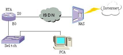
6.3.3 ISDN
ISND是综合业务数字网(Integrated Services Digital Network)的简称,是70年代发展起来的全数字服务。与PSTN相比,它实现了端到端的数字化服务,所以在连接时不再需要通过modem进行数字模拟转换,并且提供更大的接入速率(144K或2M),建立连接所需时间也大大缩短。下面是一个局域网通过ISDN实现按需拨号的模拟组网,我们可以配置路由器自动拨号建立与服务器(163/169)的连接而接入Internet。
在这种端到端的连接,我们一般采用标准DDR方式实现即可。实验配置步骤比较简单,请按照配置信息配置路由器。完成配置后的配置信息如下:
RTA#show running-config
Now create configuration...
Current configuration
!
version 1.4.1
dialer-list 1 protocol ip permit //配置dialer-list
logging console
access-list normal 101 permit ip 10.110.10. 0 0.0.0.255 any
access-list normal 101 deny ip any any //配置访问控制列表
!
interface Ethernet0
ip address 10.110.10.100 255.255.255.0
!
interface Serial0
encapsulation ppp
!
interface Bri0
encapsulation ppp
ppp pap sent-username 169 password 0 169 //配置验证
ip address negotiate //配置可以与对端协商IP地址
nat inside 101 interface //配置地址转换
dialer in-band //使能标准DDR
dialer-group 1 //配置dialer-group
dialer string 169 //配置拨号串
!
exit
ip route 0.0.0.0 0.0.0.0 Bri 0 preference 60 //配置静态路由
!
end
完成上述配置之后,打开调试信息开关(debug dialer event,debug dialer packet),配置主机的IP地址和缺省网关以及DNS(202.108.119.2)后,上网,观察路由器输出的调试信息如下:
DDR: try to find routing to 202.108.119.2 on interface Bri0
DDR: it is an interesting packet
DDR: there is not a dialer map matching this address
DDR: Find a dialer string
DDR: discard this packet
DDR: try to find routing to 202.108.119.2 on interface Bri0
DDR: it is an interesting packet
DDR: there is not a dialer map matching this address
DDR: Find a dialer string
DDR: A Link is connecting by this dialer map, waiting this Link
DDR: discard this packet
%%Interface Bri0 changed state to up.
% Line protocol ip on interface Bri0(Bri0:1), changed state to UP
DDR: try to find routing to 202.108.119.2 on interface Bri0
DDR: it is an interesting packet
DDR: there is not a dialer map matching this address
DDR: Find a dialer string
DDR: Find a Up Link on interface Bri0:1, success!
从调试信息可以清楚的看到在建立拨号的过程中,链路状态的变化。同时您还可以比较一下ISDN和PSDN二者建立拨号连接的时间,可以明显感觉ISDN建立连接更快。若硬件支持,您还可以完成ISDN对MP的支持,提高拨号连接的带宽。请自行设计完成。
小结
本实验主要完成了标准DDR的两种实现方式,灵活DDR的实现方式以及ISDN的配置。我们在实验时要仔细分析它们之间的关系和配置上的差别,注意它们的应用场合。